Shop by Category
Info
Valves / Manifolds show info...
There's a large number of dive cylinder valves out there, and getting the right one for your needs can be daunting. The Scuba Doctor dive shop has a large range to chose from and have we tried to make it easier for you with detailed info about each type of valve.
Left and Right Scuba Cylinder Valves
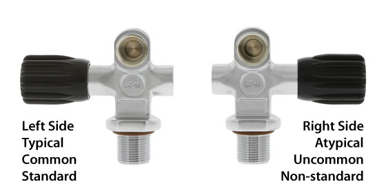
A Left valve is the typical/common/standard valve orientation used by recreational scuba divers using one cylinder. The valve opening and closing stem and hand-wheel are on the left side as you look at the valve outlet. It's also popular for use on side mount setups on the diver's left side, and for the OXYGEN cylinder on rebreathers.
A Right valve is the atypical/uncommon/non-standard valve orientation often used on the second cylinder of sidemount divers and twin cylinder technical divers. The valve opening and closing stem and hand-wheel are on the right side as you look at the valve outlet. It's popular for use on sidemount setups on the diver's right side, and opposite side stage bottles to keep the valves facing in the same direction, while keeping hand-wheels on opposite sides. It's also commonly used for the DILUENT cylinder on rebreathers.
Please Note: Be careful to properly specify whether you need a left or right valve by stating the orientation. Some manufacturers use the opposite names for their left and right valves, just to confuse everyone.
Valve Threads and Cylinder Neck Threads
!!! IMPORTANT !!! Cylinders and valve threads come in a variety of sizes and great care must be taken to ensure that you are fitting the valve to the correct cylinder. The valve thread specification must exactly match the neck thread specification of the cylinder. Improperly matched neck threads can fail under pressure and can have fatal consequences if someone is hit by the flying valve or cylinder. Only qualified scuba servicing professionals should be installing this equipment. Please ensure you have the training and experience required before purchasing this item if you intend to fit it yourself. If you are unsure, please call your local scuba technician to provide appropriate information for your system.
Australian Standard Diving Cylinder Valve Thread
Most Australian Standard aluminium and steel tanks/cylinders/bottles use a standard 3/4-inch NPSM (NGS) parallel thread, sealed by an O-ring, which has a 60° thread form, a pitch diameter of 0.9820 to 0.9873 in (24.94 to 25.08 mm), and a pitch of 14 threads per inch (5.5 threads per cm). It is torqued to 40 to 50 N·m (30 to 37 lbf·ft) on aluminium cylinders.
European Diving Cylinder Valve Threads
On most steel and aluminium diving cylinders in Europe the M25X2 ISO parallel thread, which is sealed by an O-ring and torqued to 100 to 130 N·m (74 to 96 lbf·ft) on steel, and 95 to 130 N·m (70 to 96 lbf·ft) on aluminium cylinders, is now commonly used. (M25 means the diameter of the thread is 25 mm and the X2 defines the 2 mm pitch of the thread.) On smaller cylinders where the neck isn't large enough for the M25X2 thread a M18x1.5 parallel thread, which is sealed by an O-ring, and torqued to 100 to 130 N·m (74 to 96 lbf·ft) on steel cylinders, and 85 to 100 N·m (63 to 74 lbf·ft) on aluminium cylinders is used.
Please Note: The M25X2 metric thread valves are only for use with metric M25X2 threaded cylinders. While they can be wound into a cylinder/tank with a 3/4 inch NPSM threaded neck, they will not seal properly and the combination can be very dangerous. Do not try and use these M25X2 valves on typical Faber, Catalina, Luxfer etc. cylinders purchased in Australia.
When someone tries to fit a M25 valve into a 3/4-inch BSP cylinder thread, they will get it to seal, but only after damaging the brass threads on the valve. This produces an unstable fitting which can result in the valve coming out with an incredible force that could seriously injure someone, or even kill. You have been warned.
All parallel thread valves are sealed using an O-ring at top of the neck thread which seals in a chamfer or step in the cylinder neck and against the flange of the valve.
Valve to Regulator Connection
There are two basic types of cylinder valve to regulator connection in general use for Scuba cylinders containing air:
- DIN Screw Thread Connectors — the regulator screws into the cylinder valve trapping the O-ring securely between the sealing face of the valve and the O-ring groove in the regulator. These are more reliable than A-clamps because the O-ring is well protected, but many countries do not use DIN fittings widely on compressors, or cylinders which have DIN fittings, so a diver travelling abroad with a DIN system may need to take an adaptor, either for connecting the DIN regulator to a rented cylinder, or for connecting an A-clamp filler hose to a DIN cylinder valve. We strongly recommend DIN connectors, as they are safer, which is why they are almost always used by technical divers.
- A-clamp or Yoke Connectors — the connection on the regulator surrounds the valve pillar and presses the output O-ring of the pillar valve against the input seat of the regulator. The connection is officially described as connection CGA 850 yoke. The yoke is screwed down snug by hand (over tightening can make the yoke impossible to remove later without tools) and the seal is created by clamping the O-ring between the surfaces of the regulator and valve. When the valve is opened, cylinder pressure expands the O-ring against the outer surface of the O-ring groove in the valve. Insufficient clamping force may allow the pressure to extrude the O-ring between the valve and regulator faces, resulting in a leak. This type of connection is simple, cheap and very widely used worldwide. It has a maximum pressure rating of 232 bar and the weakest part of the seal, the O-ring, is not well protected from over pressurisation.
In Europe there is now a standard for cylinder valves for scuba cylinders containing gases other than air:
- The new European Norm EN 144-3:2003 introduced a new type of valve, similar to existing 232 bar or 300 bar DIN valves, however, with a metric M26X2 fitting on both the cylinder and the regulator. These are intended to be used for breathing gas with oxygen content above that normally found in natural air in the Earth's atmosphere (i.e. 22–100%).
Most of the 200 to 240 bar valves supplied in Australia are a DIN/K convertible valve. They are made with a DIN regulator connection, but such that a DIN plug adaptor can be screwed into the DIN outlet so that an A-clamp or Yoke regulator can be connected to the valve.
Valve Pressure Rating
Yoke valves are rated between 200 and 240 bar, and there does not appear to be any mechanical design detail preventing connection between any yoke fittings, though some older yoke clamps will not fit over the popular 232/240 bar combination DIN/yoke cylinder valve as the yoke is too narrow.
DIN valves are produced in 200 bar and 300 bar pressure ratings. The number of threads and the detail configuration of the connections are designed to prevent incompatible combinations of filler attachment or regulator attachment with the cylinder valve.
- 232 bar DIN (5-thread, G5/8) Outlet/Connector #13 to DIN 477 part 1 - (technically they are specified for cylinders with 300 bar test pressure)
- 300 bar DIN (7-thread, G5/8) Outlet/Connector #56 to DIN 477 part 5 - these are similar to 5-thread DIN fitting but are rated to 300 bar working pressures. (technically they are specified for cylinders with 450 bar test pressure). The 300 bar pressures are common in European diving and in US cave diving.
Adaptors are available to allow connection of yoke regulators to DIN cylinder valves. These plug adaptors (or inserts) are rated for 200-240 bar, and can only be used with valves which are designed to accept them.
Valve Bursting Disk
Australian standards require that the cylinder valve includes a bursting disk, a pressure relief device that will release the gas before the cylinder fails in the event of over pressurisation. If a bursting disk ruptures during a dive the entire contents of the cylinder will be lost in a very short time. The risk of this happening to a correctly rated disc, in good condition, on a correctly filled cylinder is very low.
Search Our Product Range

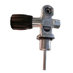
San-o-Sub DIN/K Cylinder Valve - 232 bar - Black - Oxygen Clean

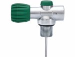
San-o-Sub DIN/K Cylinder Valve - 232 bar - Green - Oxygen Clean

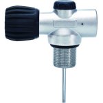
San-o-Sub DIN HP Cylinder Valve - 300 bar - Oxygen Clean

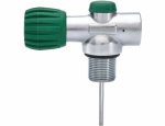
San-o-Sub DIN HP Cylinder Valve - 300 bar - Not Oxygen Clean

Ocean Design DIN/K Cylinder Valve - 230 bar - Not Oxygen Clean

San-o-Sub DIN/K Sidemount Cylinder Valve - RIGHT (232 bar) BK

San-o-Sub DIN/K Sidemount Cylinder Valve - LEFT (232 bar) BK

San-o-Sub DIN/K Sidemount Cylinder Valve - RIGHT (232 bar) GR

San-o-Sub DIN/K Sidemount Cylinder Valve - LEFT (232 bar) GR

San-o-Sub DIN/K Sidemount Cylinder Valve - LEFT (232 bar) - Gree

San-o-Sub DIN/K Sidemount Cylinder Valve - RIGHT (232 bar) BK O2

San-o-Sub DIN/K Sidemount Cylinder Valve - LEFT (232 bar) BK O2

San-o-Sub DIN/K Sidemount Cylinder Valve - RIGHT (232 bar) - Gre

San-O-Sub Rebreather X Flow Inline Cylinder Valve (232 bar) - BK

San-O-Sub Rebreather X Flow Inline Cylinder Valve (300 bar) - Gr

San-O-Sub Rebreather X Flow Inline Cylinder Valve (300 bar) - BK

San-O-Sub Rebreather X Flow Inline Cylinder Valve (232 bar) - Gr

Sonar Premium Rebreather In-Line Valve - GREEN (300 bar)
Max: 1

Sonar Premium Rebreather In-Line Valve - BLACK (300 bar)
Max: 5

Sonar Premium Rebreather In-Line Valve - BLACK (230 bar) Green
Max: 1

Sonar Premium Rebreather In-Line Valve - GREEN (230 bar)
Max: 1

San-o-Sub Dual Outlet Isolation Manifold (300 Bar) - 150 mm (5.9

San-o-Sub Dual Outlet Isolation Manifold (232 Bar) - 192 mm (7.6

San-o-Sub Dual Outlet Isolation Manifold (300 Bar) - 192 mm (7.6

San-o-Sub Dual Outlet Isolation Manifold (232 Bar) - 150 mm (5.9

Sonar Dual Outlet Isolation Captured O-Ring Manifold (300 bar) -
Max: 1

San-o-Sub Dual Outlet Isolation Manifold (232 Bar) - 212 mm (8.4

San-o-Sub Dual Outlet Isolation Manifold (300 Bar) - 192 mm (7.6

San-o-Sub Dual Outlet Isolation Manifold (232 Bar) - 212 mm (8.4

San-o-Sub Dual Outlet Isolation Manifold (232 Bar) - 150 mm (5.9

San-o-Sub Dual Outlet Isolation Manifold (300 Bar) - 212 mm (8.4

San-o-Sub Dual Outlet Isolation Manifold (300 Bar) - 150 mm (5.9

San-o-Sub Dual Outlet Isolation Manifold (232 Bar) - 192 mm (7.6

Sonar Dual Outlet Isolation Captured O-Ring Manifold (300 bar) -
Max: 1

San-o-Sub Dual Outlet Isolation Manifold (300 Bar) - 212 mm (8.4

San-o-Sub Modular HP DIN Manifold Valve - RIGHT (300 bar) - Oxyg

San-o-Sub Modular DIN/K Manifold Valve - RIGHT (232 bar) O2 BLAN

San-o-Sub Modular DIN/K Manifold Valve - LEFT (232 bar) O2 BLANK

San-o-Sub Modular HP DIN Manifold Valve - LEFT (300 bar) - Oxyge

San-o-Sub Modular DIN/K Manifold Valve - RIGHT (232 bar)

San-o-Sub Modular HP DIN Manifold Valve - RIGHT (300 bar) - Not

San-o-Sub Modular DIN/K Manifold Valve - LEFT (232 bar)

San-o-Sub Modular DIN/K Manifold Valve - RIGHT (232 bar) O2

San-o-Sub Modular DIN/K Manifold Valve - LEFT (232 bar) O2

San-o-Sub Modular DIN/K Manifold Valve - RIGHT (232 bar) BLANK

San-o-Sub Modular DIN/K Manifold Valve - LEFT (232 bar) BLANK

San-o-Sub Modular HP DIN Manifold Valve - LEFT (300 bar) - Not O


